The right agitator solution for highly viscous slurry was found by combining lab and CFD results
Slurries with representative viscosity require representative testing for scale-up
FACTS
-
While bioethanol plants are usually thought of in terms of energy production, their agitator solutions must consume as little power as possible and with reasonable investment costs.
-
Even a simple scale-up or scale-down in the bioethanol process can cause risks in the choice, design or combination of agitators.
-
The full mechanical and process design for the largest biogas fermenters or saccharification processes in bioethanol plants can be simulated reliably by combining lab and CFD results.
STARTING POINT
New processes based on non-food competitive raw materials create new demands for bioethanol agitators
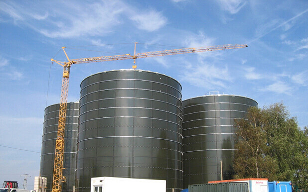
There is a growing demand for bioethanol for consumables like potable alcohol, as well as for chemicals and fuel leads. This is leading not only to larger plant sizes but also to completely new processes based on new raw materials. Cellulose-based byproducts of industry and agriculture, such as wood-based materials like sawmill dust and straw, have become applicable raw materials with the development of enzymes for breaking down cellulose and hemicellulose materials into C6 and C5 sugars. This so-called saccharification process is executed in super large vessels with top entry agitators.
These large saccharification tanks create new challenges for agitation. The rheology of agitator slurries is very special due to their non-Newtonian behavior. This makes it difficult to ensure mixing all over the tank since apparent viscosity increases rapidly as the strain rate decreases as a function of distance from the impeller.
Due to the size of the reactors, this problem cannot be solved by mixing harder. The energy consumption and equipment cost for intensive mixing would undermine the viability of the investment.
OUR SOLUTION
The key to minimizing the power required for comprehensive blending of the entire vessel is a uniform distribution of energy dissipation.
In order to distribute mixing power evenly to the agitated media, UTG applied learnings form the biogas industry. Oversized and slowly turning Theta impellers cause extra low shear and gently transfer mechanical energy to the slurry flow.
As impeller diameters between 4000–6000 mm are needed depending on the vessel size, we developed economical manufacturing methods for the impeller construction, hub and shaft design.
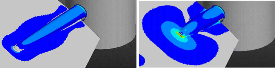
Fatigue strength calculations in particular were made for all dynamic parts of the agitator shafts, couplings, hubs and impeller wings to avoid breakdowns of the optimized construction.
IMPLEMENTATION
As slurries have so-called representative viscosity rather than the common kind of viscosity found in in polymers, measurement methods needed to be found and implemented for representative testing and data collection for scale-up procedures.
Lab tests at the UTG Mixing Technology R&D Center revealed a strong dependence of the material not only on shear rate but also on process time, as the enzymes received from the customer for tests were acting time dependently due to the decomposition of the raw material. This type of behavior makes the scale up of agitators very sensitive and increases the risk of design failure.
In order to minimize risk, measurements and the parallel integration of results into a CFD flow simulation of the full-scale process was executed. Batch tests in the laboratory gave us the required rheology information for the simulation.
The CFD flow simulation demonstrated the impeller numbers, diameters and dissipated power that would be needed to mix the material uniformly over the entire tank volume.

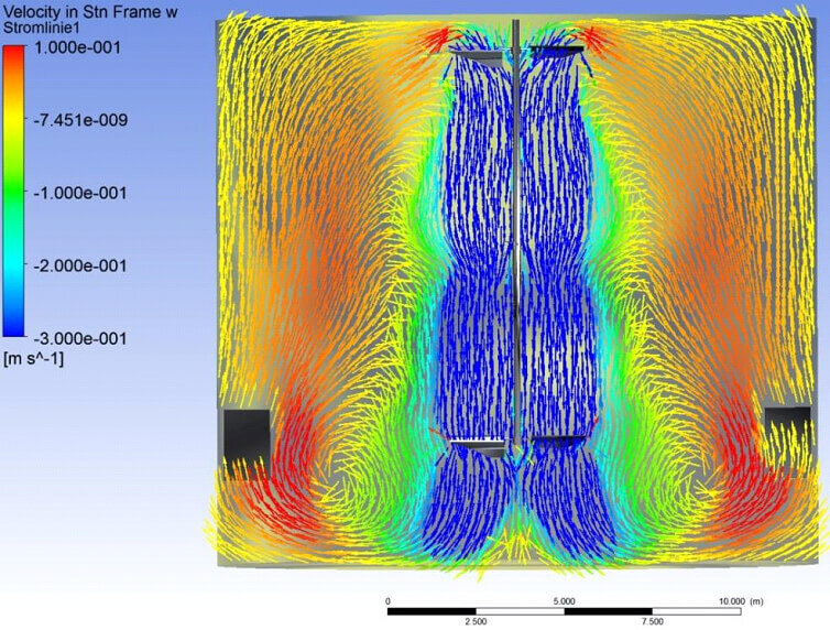
The results from the lab were then transferred to an actual agitator using CFD. FEM analysis was conducted for completing the mechanical design of these extra large agitators. Depending on the plant size, the agitators weighed between 5–25 tons as production scales were different.
RESULTS
The bioethanol plants are running well and have the capacity for future process adaptions. UTG delivered all the required agitators on time, and according to feedback the customer is fully satisfied with the plant yield: “We are glad to leave a solid economic footprint on earth to help mankind without touching competitive food resources”
Contact person from UTG for further information:
J.-P.Lindner
Technical Manager, Stelzer
+49 5641 903-62/ Mob. +49 172 9330793