Biogas reactor sizes double when customer introduces food waste products to existing raw material mixture
Full capacity achieved with larger biogas reactors
FACTS
-
Biogas production is an important part of the circular economy, in which waste is converted into renewable energy. As waste streams and energy demands grow, biogas production and the efficiency of biogas plants are also increasing to match capacity. The increase in the unit size of biogas reactors is posing challenges to mixing solutions.
-
Additional challenges are posed by the wide range of raw materials and waste to be treated. As the size of biogas plants grows, they increasingly use combinations of different raw material sources. However, the properties of the fluid to be mixed vary considerably depending on the composition of the raw material mixture. The variables of the mixture properties must be taken into account when designing the mixing solution in order to ensure the efficient operation of the biogas reactor.
-
It is important to prevent cavity formation or poorly mixed zones. The preliminary design of any large biogas reactor should always be verified by a full-scale non-Newtonian flow simulation.
STARTING POINT
The flow behavior of the customer´s new raw material mixture was not known. At the same time, plant capacity was increased. In the worst-case scenario, the electric motor could be overloaded, shutting down the entire reactor.
A biogas producer was planning to grow plant capacity by taking into production new raw material mixtures that were available locally. Previously, they had applied rather a standard mixture of maize or rice corn with manure. The flow behavior of the standard mixture was known from industrial plant tests, and non-Newtonian flow behavior variables were available.
The customer now wanted to mix in pretreatment hydrolyses and 5 fermenters along with food waste products, such as potato peals and waste French fries. The flow behavior of the new mixture was no longer known. At the same time, plant capacity was increased, and instead of increasing the number of parallel lines of normal size
fermenters (3000-5000m³), the customer increased the unit size to >8000m³. The combination is changed reactor dimensions and the flow behavior of the fluid may cause cavity formation with large zones inside the tank that would not be well mixed.
The combination is changed reactor dimensions and the flow behavior of the fluid may cause cavity formation with large zones inside the tank that would not be well mixed.
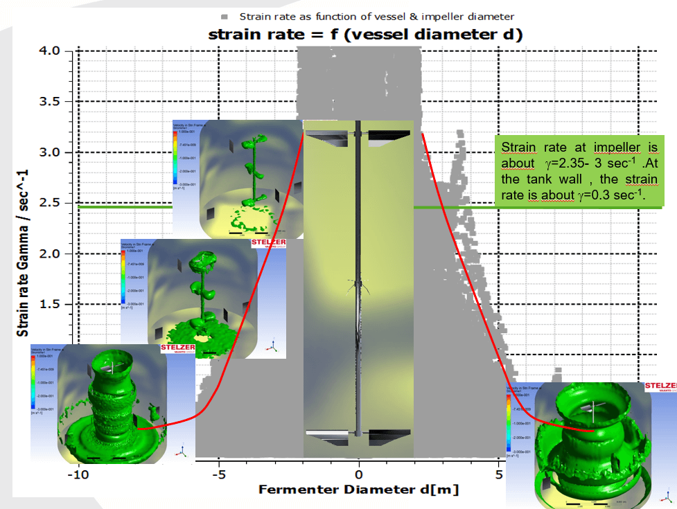
This CFD simulation of viscosities inside a biogas fermenter illustrates the strain rate at
different locations close to the impeller and close to the tank wall. Due to the low
strain rates at the tank walls, the representative viscosity rises fast.
Lab tests showed viscosity peaks that were higher than 10,000 cP depending on the shear degree of the impeller system. When viscosity rises, the fluid flow stops locally and a cavity is formed. Mass transfer in the cavitation zone fails to feed material into the chemical reactions, and the reactor will not achieve its designed production capacity.
In addition, when cavities disrupt the continuous flow between impellers, they are not able to intensify each other. The isolation of the impellers leads to increased power intake and therefore higher operating costs. In the worst-case scenario, the electric motor could be overloaded, shutting downthe entire reactor.
OUR SOLUTION
In order to ensure the right solution for the customer, UTG analyzed the optimum impeller arrangement, impeller-to-tank diameter relations, as well as impeller distances and bottom clearance.
We then utilized the results from this extensive study for our biogas agitator design program. This program allows us to determine cavity sizes for different raw material mixes and optimize the impeller configuration to achieve optimal mixing of all the contents in the tank.
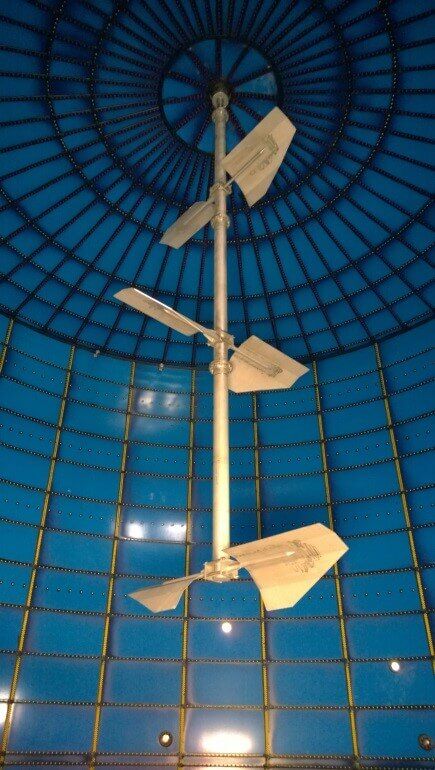
The result was a 3-stage STELZER Theta impeller system with specific blade angles and wing shape to handle the demanding mixing tasks of blending, gas output, suspension and reversed suspension, meaning dragging floating material into reaction zone.
It turned out that the power demand for the large units was sensitive to the clearance of the upper impeller to the surface of the gas/liquid. With long distances, floating layers could not be dragged into the bath. When the distance was too short, circulation between the upper impeller and lower impellers was cut off, so floating material was only circulating in a short loop near the surface without delivering material to the lower bath.
IMPLEMENTATION
Empirical data of different raw material mixtures was analyzed in terms of non-Newtonian flow behavior, the required specific power input and impeller configuration.
The customer delivered deep-frozen samples of raw materials for laboratory test runs. UTG´s laboratory is extremely well equipped with numerous test stands. Hundreds of impellers of different shapes and diameters enable the fast set up of different mixing configurations. The mixing rig is instrumented and equipped with special computer
software for measuring and data processing of scale-up procedures.
These tests determined the optimal preliminary design and non-Newtonian flow parameters for numerical simulations. The laboratory-scale preliminary design was then verified with a detailed numerical model (CFD) of the full-scale 8000m³ reactor.
Data was also used for creating our own special biogas agitation program, which can now be used for a wide range of raw materials without the need for further laboratory tests.
RESULTS
We have since applied our biogas agitation design program to other plant sites with more than 50 units delivered over the past 3 years.
The original customer is fully satisfied with the operations of the plant. Full design capacity was achieved for a variety of raw material mixtures, and no problems in flow circulation have been detected.
Further information:
J.-P.Lindner
Technical Manager, Stelzer
+49 5641 903-62/ Mob. +49 172 9330793